When differentiating according to the flow pattern, the influent can pass through sub-surface planted gravel filters either horizontally or vertically. The different flow pattern relates to different designs and different treatment results.
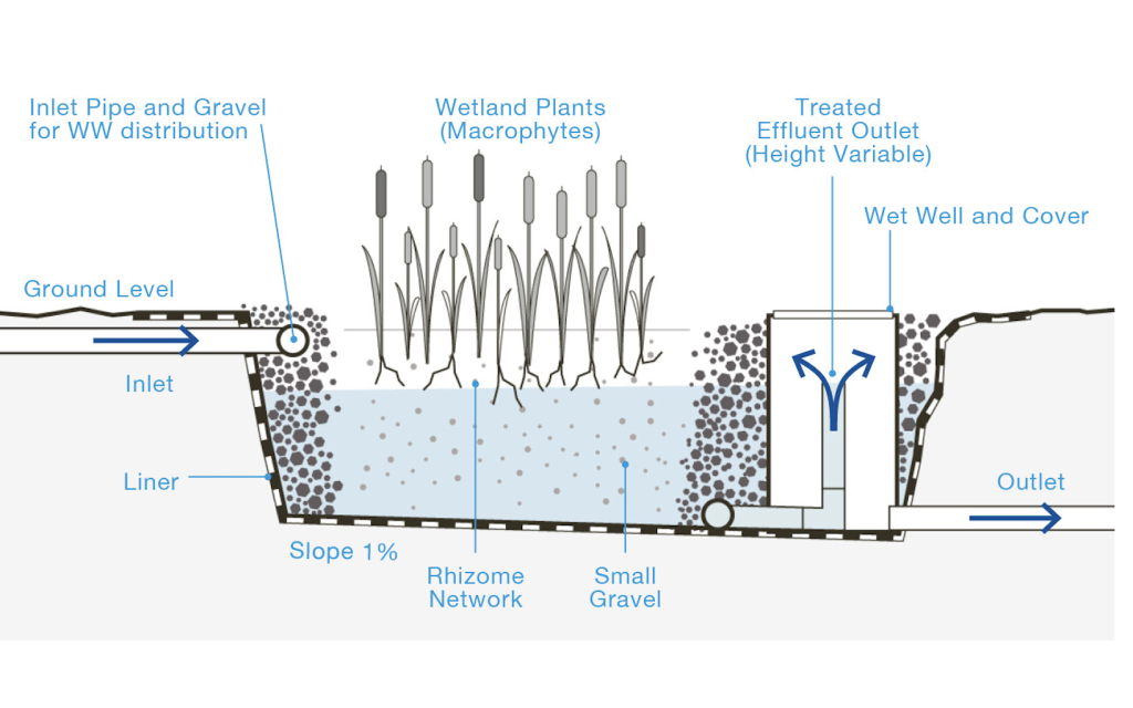
Cross-Sectional View of a Horizontal Planted Gravel Filter
In a Horizontal Planted Gravel Filter (HPGF), the influent enters at one end, passes through the filter horizontally and exits at the other end of a large gravel and sand-filled basin planted with wetland vegetation. These filters are often wide and shallow, with plants strategically arranged in rows along the flow path. The plants are usually positioned near the water’s surface, and their root systems extend horizontally into the water. As water flows through these roots, contaminants are removed.
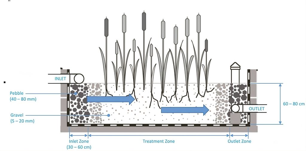
Three zones are to be distinguished: inlet, treatment, and outlet zone. The inlet zone has pebbles with larger diameters (40 – 80 mm) as a filter medium from the top to the bottom of the system to minimise the risk of clogging and to enable the distribution of influent entering through a perforated inlet pipe. The treatment zone has gravel with a smaller diameter (5 – 20 mm) as a filter medium that must be clean without dust or sludge to avoid rapid clogging.
Cross-Sectional View of a Horizontal Planted Gravel Filter Showing Different Zones of Filter Media and Flow Direction of Influent
In comparison, in a Vertical Planted Gravel Filter (VPGF), the wastewater enters at the top and flows downward through a vertically oriented bed of planted gravel. Vertical filters are often taller and narrower, with a smaller surface area relative to their depth. In these systems, plants are distributed throughout the entire depth of the filter bed. Their root systems extend vertically along the whole depth of the filter. As wastewater flows from the top to bottom, it encounters roots, where contaminants are removed.
Cross-Sectional View of a Vertical Planted Gravel Filter
Due to the vertical flow, the filter system has improved oxygen distribution compared to HPGF, promoting aerobic conditions throughout the entire filter depth. Nonetheless, there is a higher risk of clogging as wastewater must pass several treatment layers: filtration, transition, and drainage. For effective treatment and to minimise the risk of clogging, it is important to respect substrate properties, effective grain size and the uniformity coefficient when selecting filter media. Using sand for the filtration layer shows an increased permeability reduction due to sediment accumulation, but sludge accumulates at the surface, avoiding a higher depth of clogging.
Sectional View of a Vertical Planted Gravel Filter Showing the Different Layers of Filter Media and Flow Direction of Influent
The two filter systems have different operation modes to achieve an efficient treatment. The horizontal filter system requires feeding in small, consistent doses of effluent throughout the day (continuous feeding). It is crucial to prevent the sudden discharge of large amounts of wastewater at any cost. On the other hand, the vertical filter system requires a cycle of alternating between feeding and aeration/resting periods. Aeration/resting periods should be maintained during this cycle, lasting at least 2 to 3 days, ensuring proper time for biological processes. Some practices even advocate for doubling the time allocated for resting and aeration. The level of aeration is intricately linked to the plant species present, as they actively contribute to sludge mineralisation. Moreover, the plants enhance aeration by moving the stems, which are swayed by the wind, promoting increased infiltration. To ensure sufficient aeration time between batches, the VPGF is usually divided into cells by separation with walls or membranes, except for very small single-family systems.
Both HPGF and VPGF contribute to cleaner effluent. Still, the choice between these two filter types depends on factors like space availability, design objectives and the specific requirements of the treatment process.
The following table summarises the differences between the two types of planted gravel filters.
Horizontal Planted Gravel Filter
Vertical Planted Gravel Filter
Flow Direction
Primarily horizontal. Influent flows horizontally through a layer of plated gravel, which may be situated just below the surface.
Primarily vertical. Influent flows from the top to the bottom of a vertically arranged bed of planted gravel.
Depth (m)
0.6 – 0.8
0.8 – 1.2 (top to bottom: 30 – 40 cm filtration layer, 10 – 15 cm transition layer, 15 – 20 drainage layer)
Filter media
Small, round, evenly sized gravel with diameter of 5 – 20 mm; inlet and outlet
Filtration layer: sand with a diameter of 0.25 – 0.4 mm; transition layer: pea gravel with a diameter of 3 – 10 mm; drainage layer: coarse gravel with a diameter of 20 – 40 mm
Required Surface Area
20 m² per m³ influent and day or ≈3 m2 per person in warm regions
< 10 m² per m³ influent and day
Layout
Usually wider and flatter with a larger surface area relative to the depth.
Usually taller and narrower with smaller surface area relative to the depth.
Feeding Mode
The system can be continuously fed.
Vertical filters are aerobic and are fed by batches (to allow aeration during the rest period); electric pumps or manual opening valves are commonly needed to feed multiple filters alternately.
Risk of Clogging
Clogging occurs after 10 to 25 years or more (depending on the quality of effluent to be treated).
Clogging occurs regularly (for example 1 year), and periodic cleaning is required.
System Strengths
Efficient reduction of the concentration of organic matter (BOD, COD), SS, N, and P.
The pathogens concentrations are also strongly reduced (by a factor of 1,000 or 10,000).
The flow in a horizontal filter is a “Subsurface flow” under the surface of gravels, and there is no contact with animals or humans and no odour.
Efficient reduction of the concentration of organic matter (BOD, COD), SS, N, and P.
The pathogens concentrations are also strongly reduced (by a factor probably lower than the horizontal system because of shorter retention time).
It is natural, producing reeds and compostable plants for the population and the field workers.
The sludge accumulates on the surface of the filter and is theoretically more straightforward to remove than the sludge in the gravel of a horizontal filter.
Comparison of Horizontal and Vertical Planted Gravel Filters
For further information, please click on the Materials tab at the top of the page.
Further Reading:
Constructed Wetlands Manual by the United Nations Human Settlements Programme: Introduction to planted gravel filters as well as detailed elaboration on design, construction and O&M. It also includes several case studies. (Link)
This website uses cookies so that we can provide you with the best user experience possible. Cookie information is stored in your browser and performs functions such as recognising you when you return to our website and helping our team to understand which sections of the website you find most interesting and useful.
Strictly Necessary Cookies
Strictly Necessary Cookie should be enabled at all times so that we can save your preferences for cookie settings.
If you disable this cookie, we will not be able to save your preferences. This means that every time you visit this website you will need to enable or disable cookies again.
3rd Party Cookies
This website uses Google Tag Manager to collect anonymous information such as the number of visitors to the site, and the most popular pages.
Keeping this cookie enabled helps us to improve our website.
Please enable Strictly Necessary Cookies first so that we can save your preferences!